|
ACES-PSC: Design of pretensioned girders |
|
ACES-PSC performs the design of pretensioned concrete Super-T beams to the Australian Standards bridge design code AS5100.5 (2017). However, the module has been developed in a way that will allow you to easily change the design equations to suit other section types and codes (see later). The main assumptions and restrictions embodied in this version are as follows:
| |
- Unless otherwise stated, calculations are based on the general approach given in AS5100.5 - 2017.
|
- The concrete compressive block may lie within the insitu concrete slab, flanges or web.
|
- The composite Neutral Axis may lie above or within the void.
|
- Two options are provided for performing the Ultimate Moment check (one based on the Simplified Approach and the other on the Strain Compatibility Method).
|
- Serviceability crack checking is performed using the Strain Compatibility Method.
|
- The effects of passive (non-prestressed) reinforcement are included in the analysis.
|
The module can either be accessed directly from within the main ACES program or run in stand-alone mode. If run from within ACES all section properties and job attributes for the selected girder will be automatically transferred into the PSC module. Note that member forces can also be imported from the current ACES model, but this is not done automatically - you must choose the relevant load cases and envelopes. Design values can also be entered directly into a table or pasted into the table from other applications (such as an EXCEL spreadsheet).
Click here
for a description of the design methodology adopted in ACES-PSC.
Click here to view an album of typical screen shots from the module (note that these images are of the multi-section version, which is currently undergoing rigorous checking).
|
| |
Features |
|
|
Design Standards: ACES-PSC performs the design of standard AS5100 open and closed trough pretensioned Super-T beams. However, section properties data for non-AS5100 Super-T sections can easily be saved to the Super-T database and accessed when needed. Alternatively, section properties for non-standard shapes can be calculated manually and entered directly into the appropriate data fields. Click here to view the default section properties database file (Secprops.txt).
|
|
|
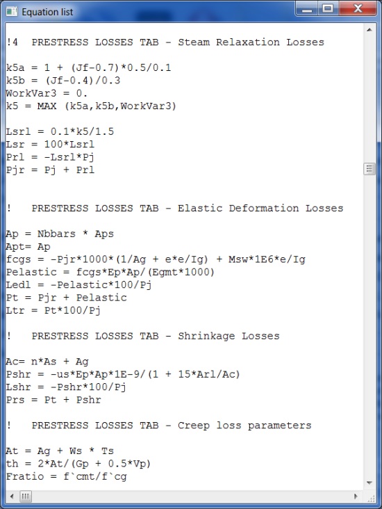
Design Equations: While the design method incorporated into ACES-PSC is based on the AS5100 code, all equations and algorithms can be changed and customised to suit your own methodology. A separate and unique equations file sets out the design process. This is a text file that can be edited using any convenient text editor (such as NOTEPAD or WORD). Equations and algorithms can be modified, deleted or added to suit your own design requirements using a set of simple rules. Logical functions such as IF..THEN, ITERATE, LOOP, MAX, MIN are available to handle complex algorithms involving some degree of logic. Click here to view the equations file used by the PSC module.
|
|
|
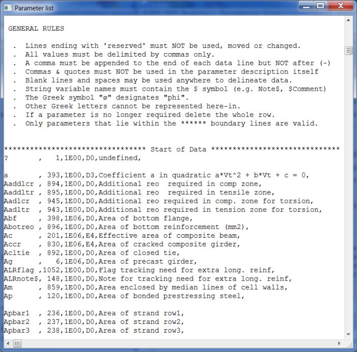
Parameter Definitions: Parameter definitions used in dialog boxes and equations can be changed to suit local conventions. If you don't like the parameter names or descriptions used by ACES-PSC you can change them to suit your own tastes. New parameters can also be defined in situations where you would like to add your own equations, customised buttons and customised dialog boxes. Parameter definitions are stored in a separate text file that can be edited using any convenient text editor (such as NOTEPAD or WORD). Click here to view the parameter description file incorporated into the PSC module.
|
|
|
Analysis: An EXCEL spreadsheet-style analysis process is used. Change a parameter anywhere in the module, click the Recalculate button, and the entire design is redone.
|
|
|
Calculation Logs: Calculation logs give detailed descriptions of every equation used in the analysis as well as the immediate value of every parameter and variable set during the analysis process. Calculation logs are available for different levels of design detail at the click of a View calcs button - either for the entire design; a specific part of the design (e.g., the section that only checks for shear); or for a sub-set of that one part (e.g., the check for flexural shear cracking). Calculation logs can be saved as text files at any stage of the design. The log is also saved with the model file. Click here to view a typical calculation log.
|
|
|
Results: Detailed results for every design check are displayed for every section along the girder. Values that exceed allowable limits or calculated capacity levels are highlighted in red, and interaction diagrams for serviceability, ultimate moment, ultimate shear and torsion enable inadequacies to be quickly spotted. Click here to view a typical interaction diagram.
|
|
|
Reports: Two different types of output reports are available; both are fully customisable. At the individual section level the reports have been created in HTML (web browser) form. The full design logic and all equations and associated parameter values are shown in the report. As a consequence, reports can be customised to suit your needs using standard HTML editors. Reports not involving variable-length tables can also be edited using WORD,although they must be saved using the filter option. Click here to view a typical HTML report proforma. For multi-section designs, report proformas have been developed as text files that can be edited just as easily. A simple set of print statements allow results at all sections selected for design to be quickly generated.
|
|
|
Default Settings: A large number of parameters can be preset and saved to a defaults file. They will be auto-loaded into the module when a new design is initiated. Default parameters can be customised i.e., you determine which parameters are included in the default parameter set and what their initial values are. This is a text file that can be edited using any convenient text editor (such as NOTEPAD or WORD). Click here to view a typical default parameter definitions file.
|
|
|
Custom Buttons and Dialog Boxes: Up to two additional customised buttons and their associated dialog boxes can be created for each tab in the PSC module. New parameters can be created and added to these dialog boxes, either as data entry fields or results fields. The proforma that enables this customisation is a text file that can be edited using any convenient text editor (such as NOTEPAD or WORD). Click here to view a typical default customisation file.
|
|
|

|
Design Methodology
|
The full design logic and all equations and associated parameter values used by ACES-PSC are incorporated into the various output reports produced by the module. To review the methodology used in the design process either click on one of the report proformas listed below or click here to view the full equations file.
In the report proformas you will notice that the symbol, or name, associated with any particular parameter is enclosed in curly brackets. When you click on any one of the Print this page buttons in the PSC module the actual numeric values of all of these parameters will be substituted in place of the symbols. The following report proformas incorporate the full design methodology on which this PSC module is based. A list of restrictions and omissions is given in the first report (Job ID data and restrictions).
|
|
|
| Note again that although the design has been based on the AS5100 code, all equations and algorithms used in the design process can be changed and customised to suit your own design methodology. This can be done by editing the equations file using any convenient text editor (such as NOTEPAD or WORD). Equations can be modified, deleted or added to suit your own design requirements using a set of simple rules that are described at the beginning of the file. (Note that relevant report proformas shown above may also have to be changed to reflect any modifications made to the equations file). |
| |
|
|
|
Screen Shots
|
(Note that some screen images may not always represent the current version of the program)
|
|
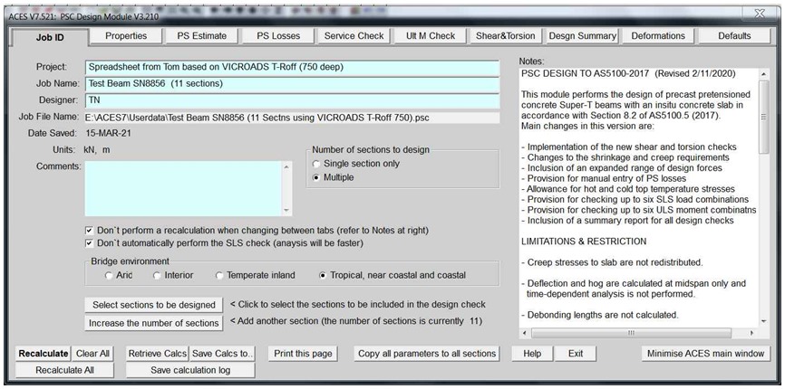
Job ID tab |
| |
|
|
|
| |
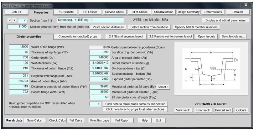
Section properties tab |
| |
|
|
|
| |
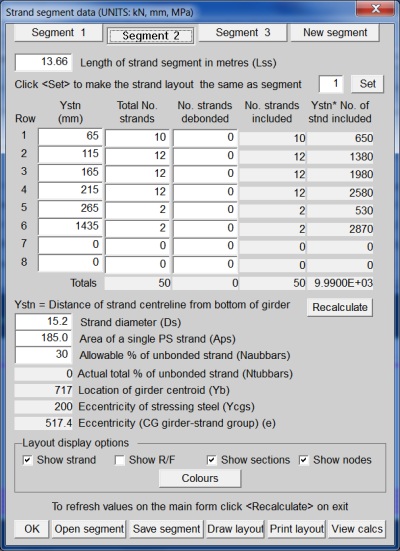
Strand segment layout dialog box |
| |
|
|
|
| |
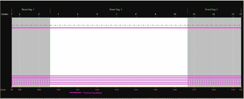
Strand layout diagram (click the "Draw layout" button to display): |
| |
|
|
|
| |
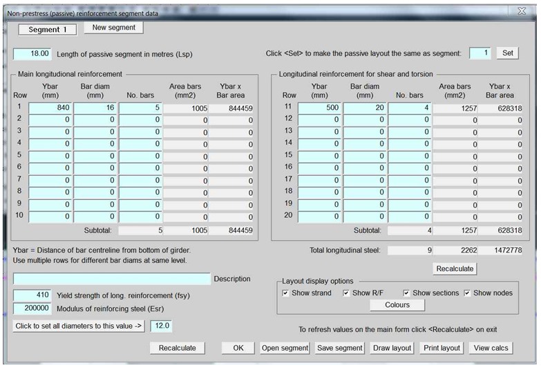
Passive reinforcement layout dialog box: |
| |
|
|
|
| |
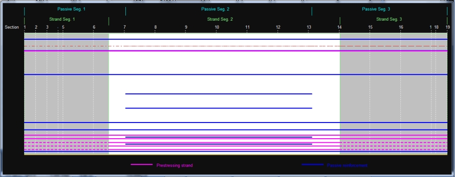
Strand and passive reinforcement diagram |
(The "Show strand" and "Show R/F" boxes are both ticked): |
| |
|
|
|
| |
|
|
| |
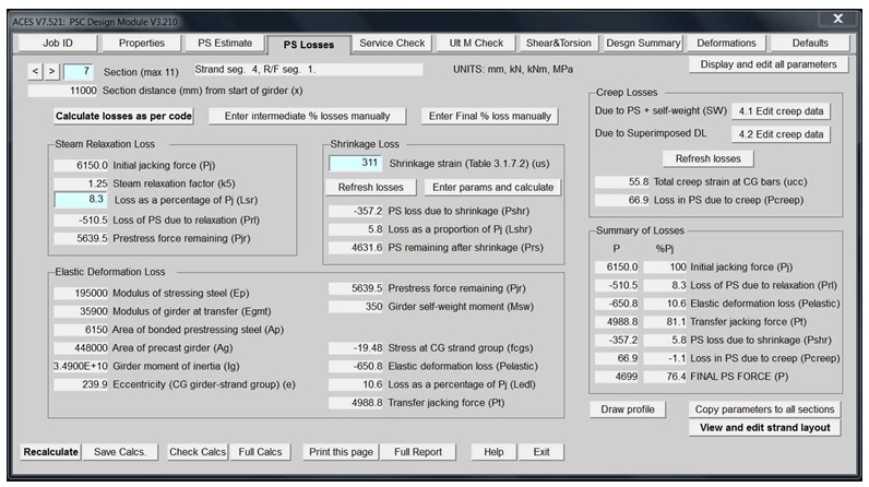
Prestress losses tab |
| |
|
|
|
| |
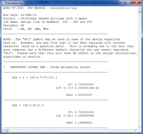
Prestress losses - calculation log relevant to this tab |
(Click the "Check calcs" button to display) |
| |
|
|
|
| |
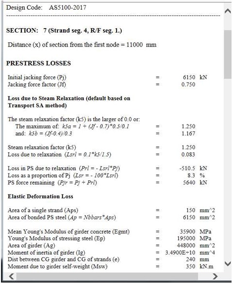
Prestress losses - detailed design report |
(Click the "Print this page" button to display this report) |
| |
|
|
|
| |
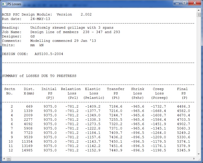
Prestress losses summary report for all selected sections along girder |
(Displayed when the "Full report" button is clicked and the view report option is selected) |
| |
|
|
|
| |
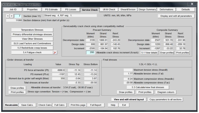
Serviceability check |
| |
|
|
|
| |
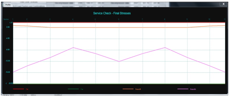
Serviceability check - final stresses diagram |
(Displayed when the "Draw profiles" button is clicked) |
| |
|
|
|
| |
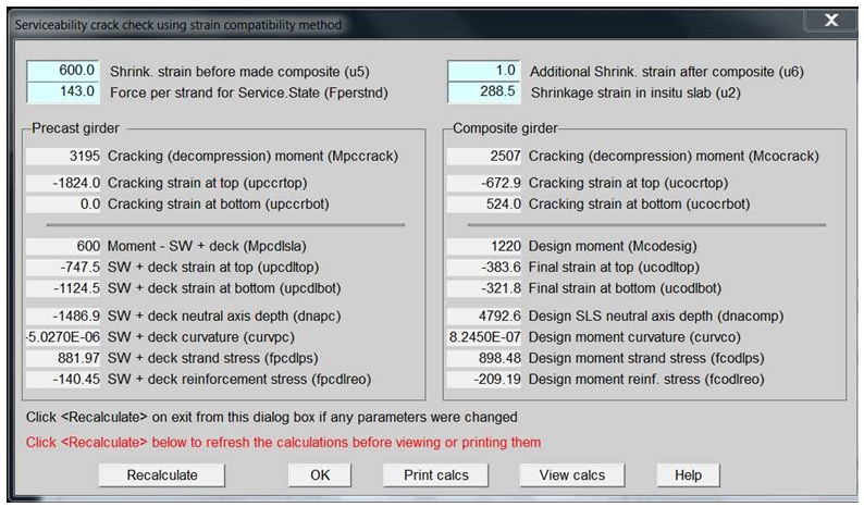
Serviceability crack check using strain compatibility dialog box |
(Displayed when the "5.1 View Details" button is clicked) |
| |
|
|
|
| |
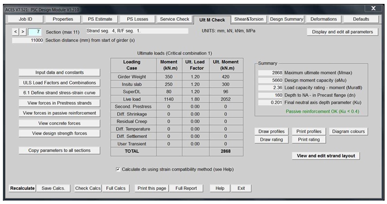
Ultimate moment check |
| |
|
|
|
| |
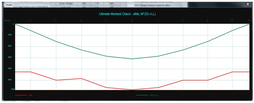
Ultimate moment check distribution diagram |
| |
|
|
|
| |
Shear check and reinforcement design |
| |
|
|
|
| |
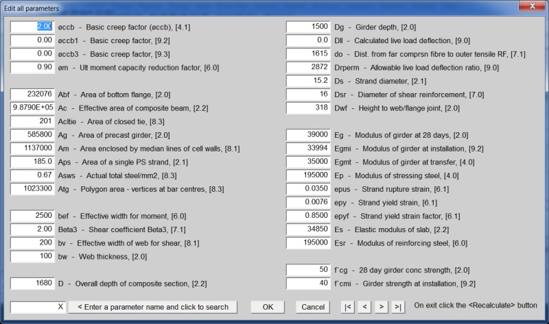
Display and edit all parameters - this button is on all tabs |
(This form is displayed when that button is clicked) |
| |
|
|
|
| |
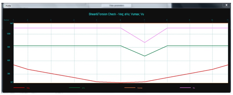
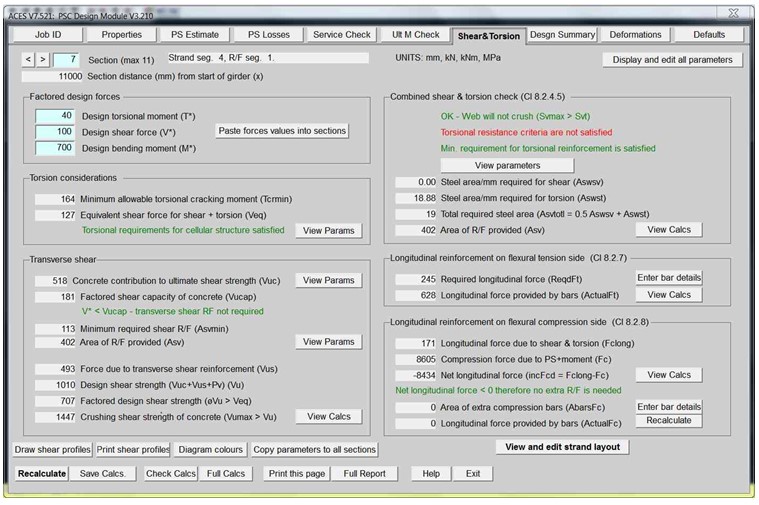
Shear torsion check |
| |
|
|
|
| |
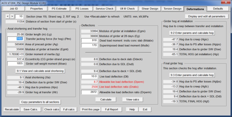
Deformations and hog |
| |
|
|
|
| |
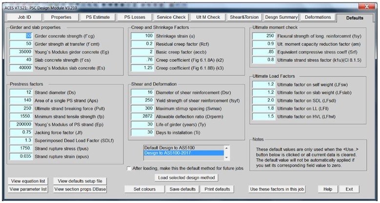
Defaults tab |
| |
|
|
|
| |
Defaults tab - "View Parameter List" |
| |
|
|
|
| |
Defaults tab - "View Equation List" |
| |
|
|
|
