|
|

|
|
Static demo of main program featuresThe following static screen images will give you a good idea of the key features found in this program, particularly with regard to modelling moving vehicle loads. If you would prefer not to scroll through the demo images click here to download the evaluation version now. Otherwise scroll through the screen images or select from one of the following topics:
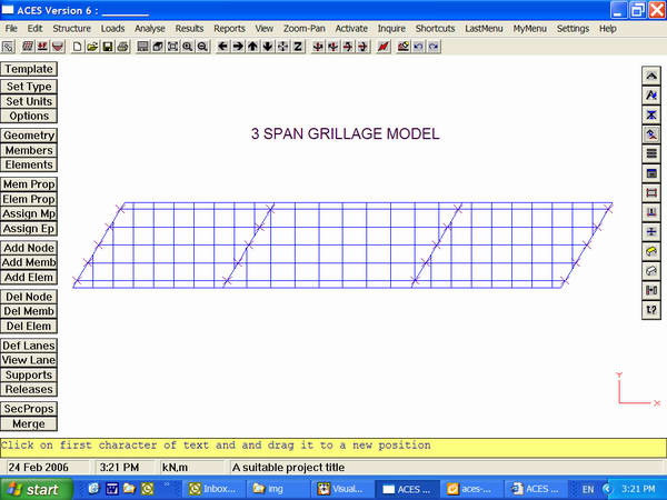
Typical Grillage ModelUsing a large set of predefined templates, ACES contains all of the features needed to quickly and easily create the structure geometry. Supports are automatically inserted under main longitudinal girders and member property types are colur-coded and assigned to logical parts of the model (such as girders, transverse beam elements, diaphragm supports, cantilever edge beams and so on). All you have to do is enter actual section and material properties. (Refer to the Features page for further details).
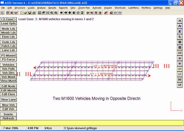
Moving Vehicle LoadsMoving vehicle load cases are a snap to create. Use the predefined AUSTROADS loadings (including the new M/S1600 class) or create your own vehicles, save them to the data base, then add them to the model. Up to five vehicles can be added to any one load case. They can all be identical or all different and each vehicle can have its own unique travel path. (Refer to the Features page for further details).
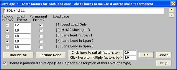
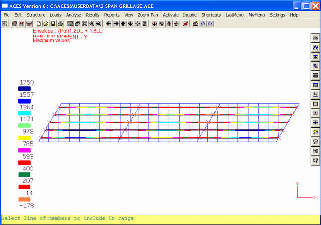
EnvelopesSpecifying envelopes with ACES is equally easy. After all load cases have been created, click the red lightning bolt icon to perform the analysis. After the problem has solved, select a range of members to interrogate, then click on Results / Envelopes and fill in the dialog box as shown below. (Refer also to the Features page for further details).
Create as many envelopes as you like, without having to re-analyse the problem again! In fact, ACES will allow you to create envelopes from any of the other envelopes you have already defined!
Graphical ResultsOnce an envelope has been specified, select the type of results (moments, shears, deflections, reactions etc) you would like to view from a menu and dialog box, then display them in one of four different ways:
Tabular ReportsAll results can be viewed and printed in tabular form. For moment, shear and torsion envelopes in frame and grillage models, ACES allows you to report on the maximum and minimum values of one of the selected force vectors together with corresponding values of all others. The loading number that causes that maximum or minimum value is also shown. This becomes particularly useful for determining loads on bearings and substructure. (Refer also to the Features page for further details).
In the example shown above, a summary is given at the end of the report of the maximum values of the selected vector (My in this case) at both the start and end nodes of the relevant member, together with the corresponding values of the other applicable force vectors (shear and torsion). The loading numbers contributing to the maximum values are also shown (in brackets).
|
Click on our name to send us an email @ aces
The ACES name and trademark is copyrighted to ACES Bridge Analysis Systems. Website created by Solveit All